Two channel audio source switch with Wi-Fi
The HiFi system in my livingroom is centered around an amplifier from the ’80s. There are a few audio sources connected to it:
- A television
- A Chromecast Audio
- A record player
The amplifier is powered through a smart plug that, through the power of Home Assistant, turns on whenever there is an active audio source and gets shut when there is none. Although nice and very convenient, this is not enough from keeping the listener from fiddling with the amplifier’s switches to choose the right audio source, since it gets toggled quite often between the TV and the Chromecast.
The ideal solution would be to automate the switch on the amplifier, but this requires some ugly mechanics around the switch, or an invasive internal modification. A simpler way to go is the use of a relay to phisically switch audio source when needed. To simplify the solution I decided to exclude the record player from the problem, since it is rarely used and it needs the listener to set the right volume on the amplifier anyway.
Surprisingly enough, I didn’t find any commercial audio switcher that meets my needs. There are plenty of audio switchers on Amazon, but none of them is controllable remotely. However, there are a few DIY solutions out there. At the end I decided to make my own, basing my solution on Wi-CASSS, a design made by Govindan Unni.
I chose to go with a relay-based design because it’s simple to make and gives the best audio insulation.
BOM
Main circuit
| Item | Qty |
|---|---|
| ESP8266 ESP-01s | 1 |
| OMRON G6S-2 (5V) signal relay | 1 |
| Panel 3.5 mm Stereo jacks | 3 |
| 1N4007 diode | 1 |
| Micro USB breakout board | 1 |
| 5V to 3.3V AMS1117 breakout board | 1 |
| BC547 transistor | 1 |
| 1 kΩ resistor | 1 |
| 220 Ω resistor | 2 |
| 5mm round LED | 2 |
| 10µf capacitor | 1 |
| 100µf capacitor | 1 |
Front panel
| Item | Qty |
|---|---|
| 5mm round LED | 2 |
| Momentary push button | 1 |
After some shopping on AliExpress, the total cost amounted to almost 14 euros shipped (excluding LEDs and reistors which I already have) including many spare components, enough to make at least two complete circuits.
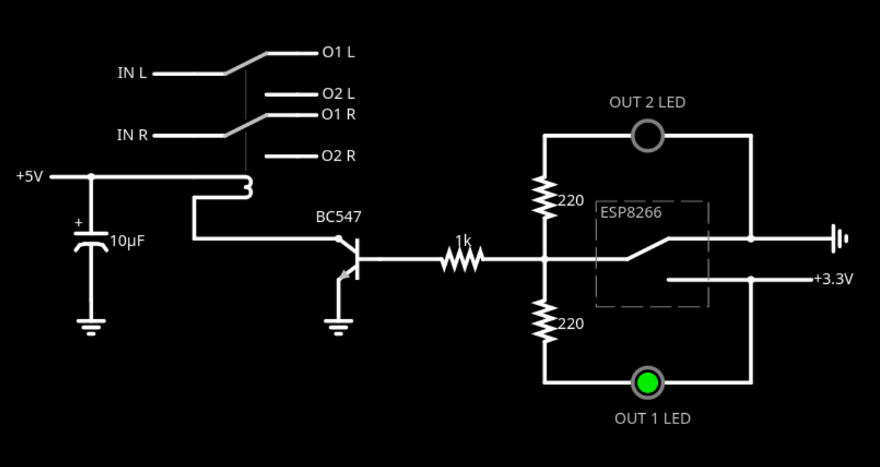
Schematics
Original schematic. Redesigned relay driver circuit.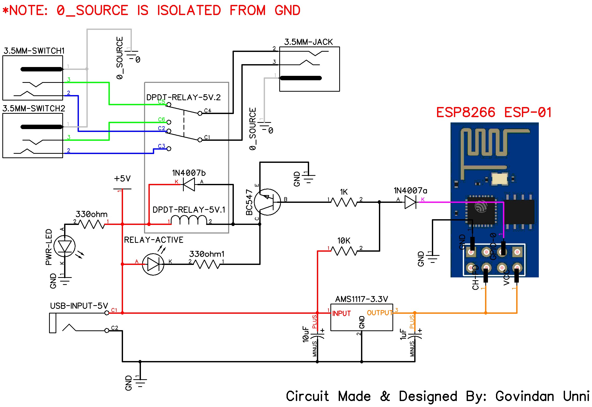
I realized the circuit on perfboard since it’s quick and easy to make circuits out of.
In the following picture you can see and early attempt at placing the components. This first try still used the original Wi-CASSS’s schematic (as you can see by the extra diode in the top left corner of the picture). Early components placement prototype.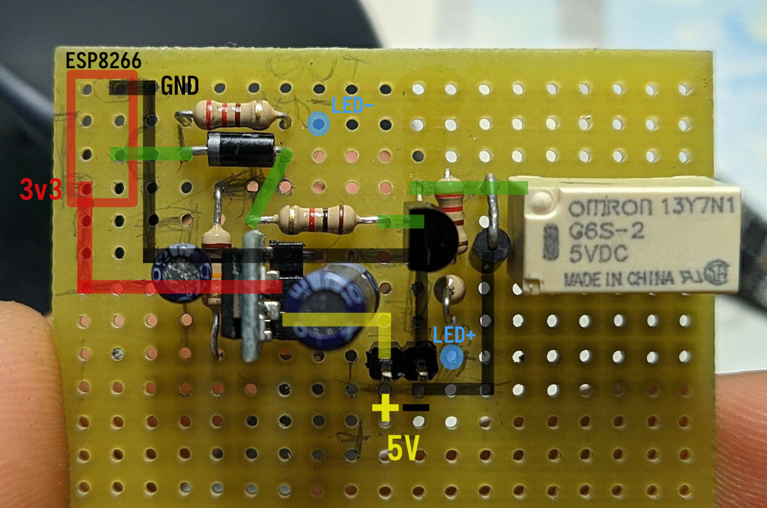
Enclosure
I decided to design and 3D print my own enclosure. I didn’t want to have dangling wires coming out of it, so all external peripherals are detachable.
Power comes from a micro-usb breakout board, external connections to the front panels are handled by a small perfboard with pin headers. To hold all the connectors in place I designed the enclosure with supports and holes to handle that. Supports in CAD vs IRL. The micro-USB board is held in place with superglue and two copper pins (out of thick wire core).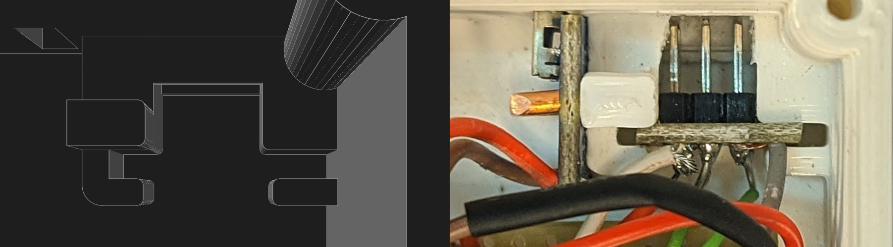
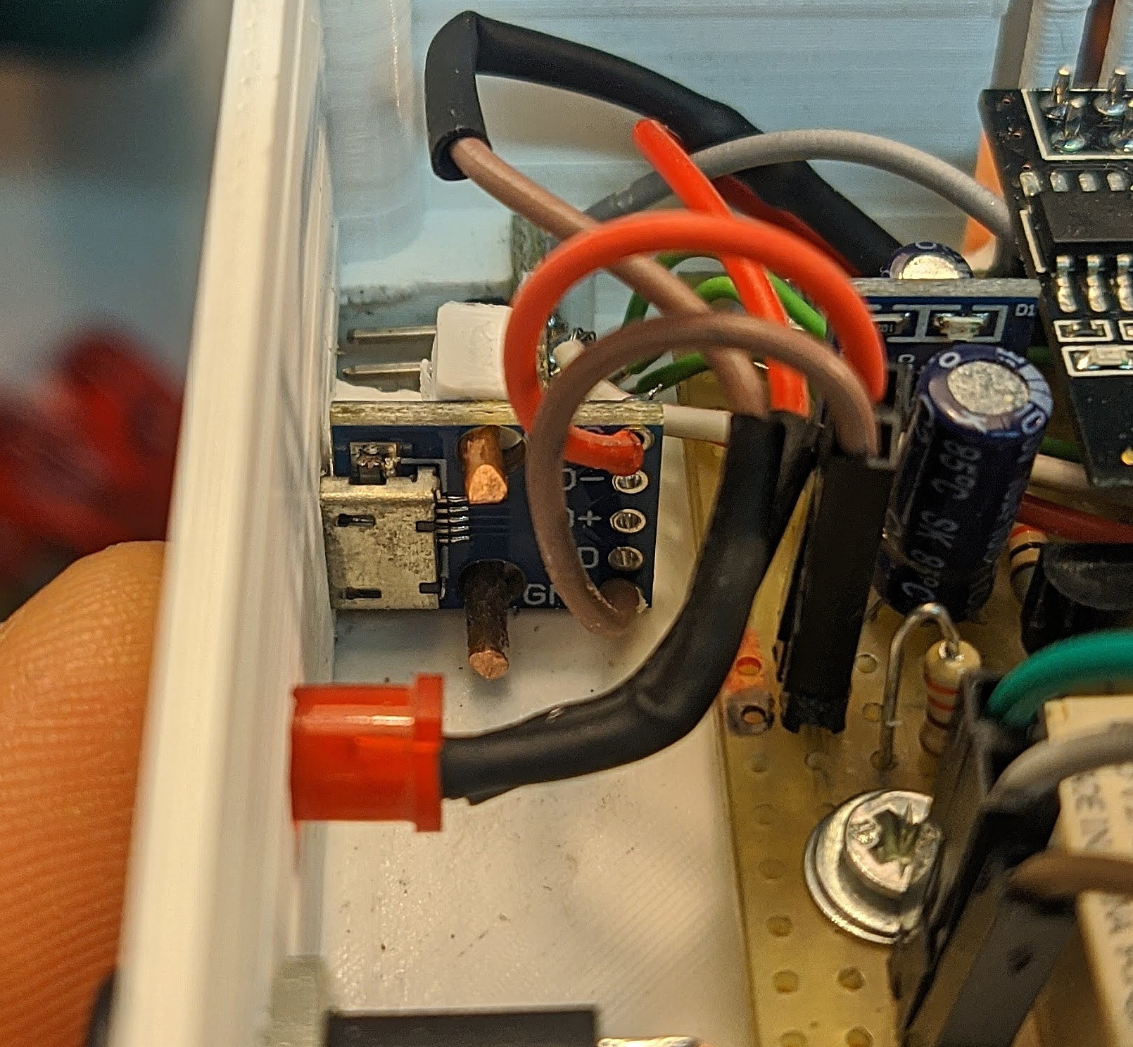
After drilling the board, it’s ready to be fit into the case. The circuit is secured using 2 screws; It was supposed to be three but a few drilling errors prevented that. The board still feels firm anyway.
A late addition to the circuit is the power LED, which is soldered to the 3.3V line, with its current-limiting resistor on the wire, since it wasn’t planned in my original design. It wont win any beauty contest, but it works. The print quality is far from perfect, but this box will not be visible anyway.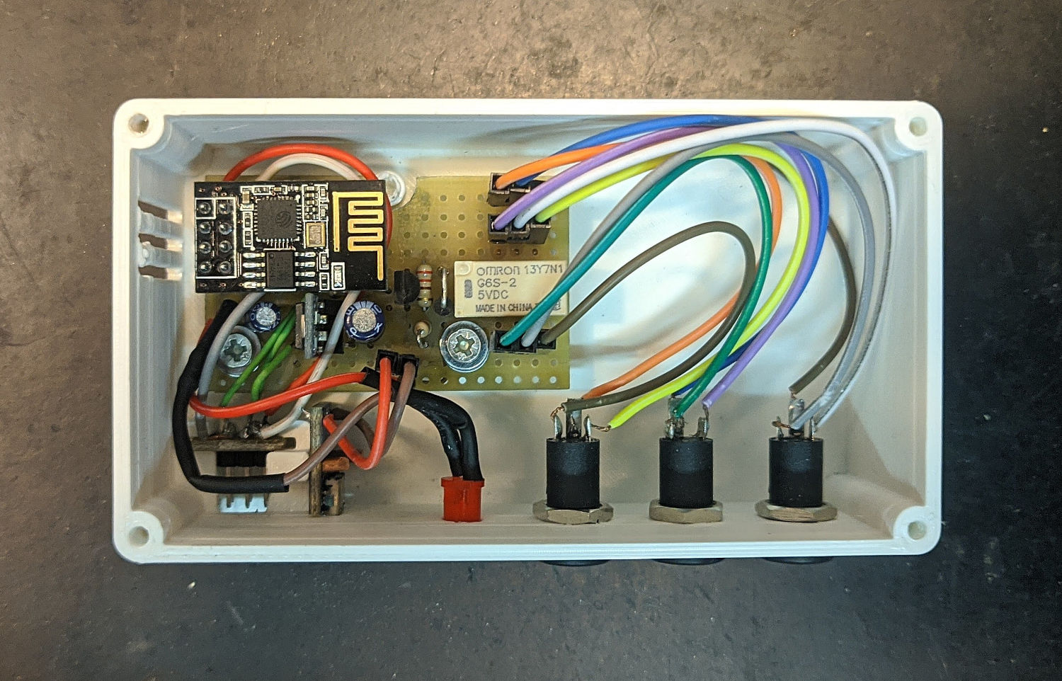
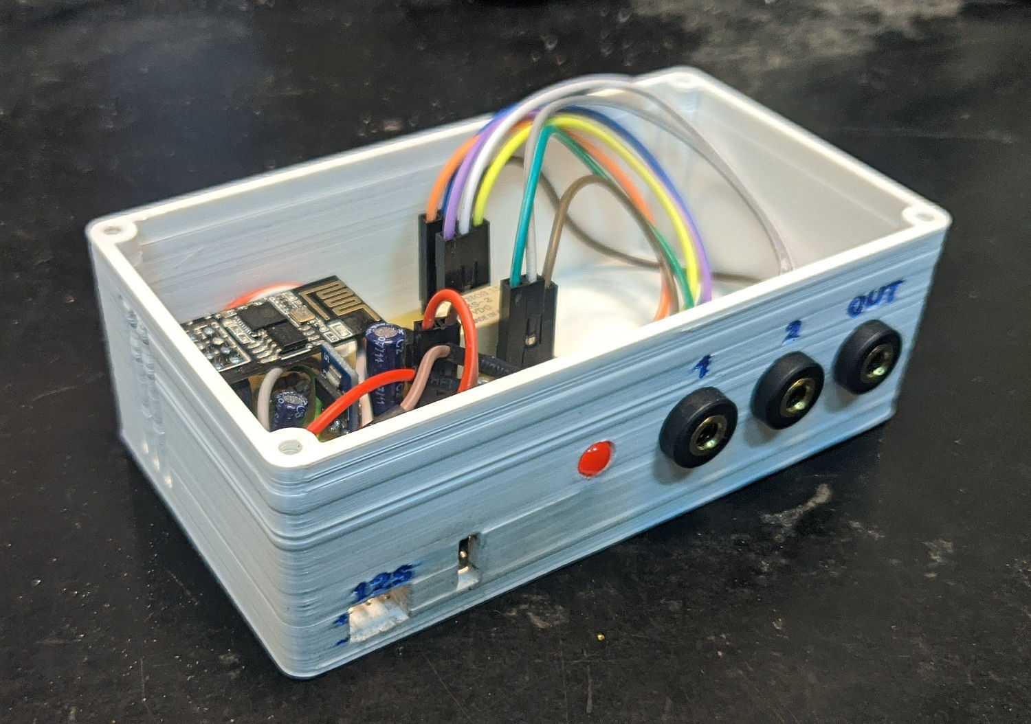
The top cover is a thin sheet alluminium panel cut to dimension and screwed on top.
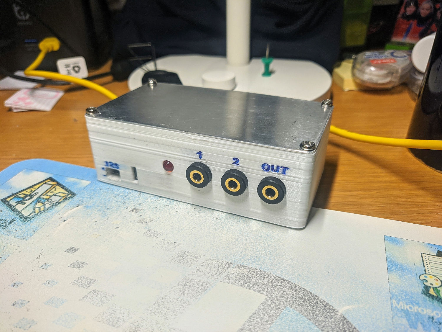
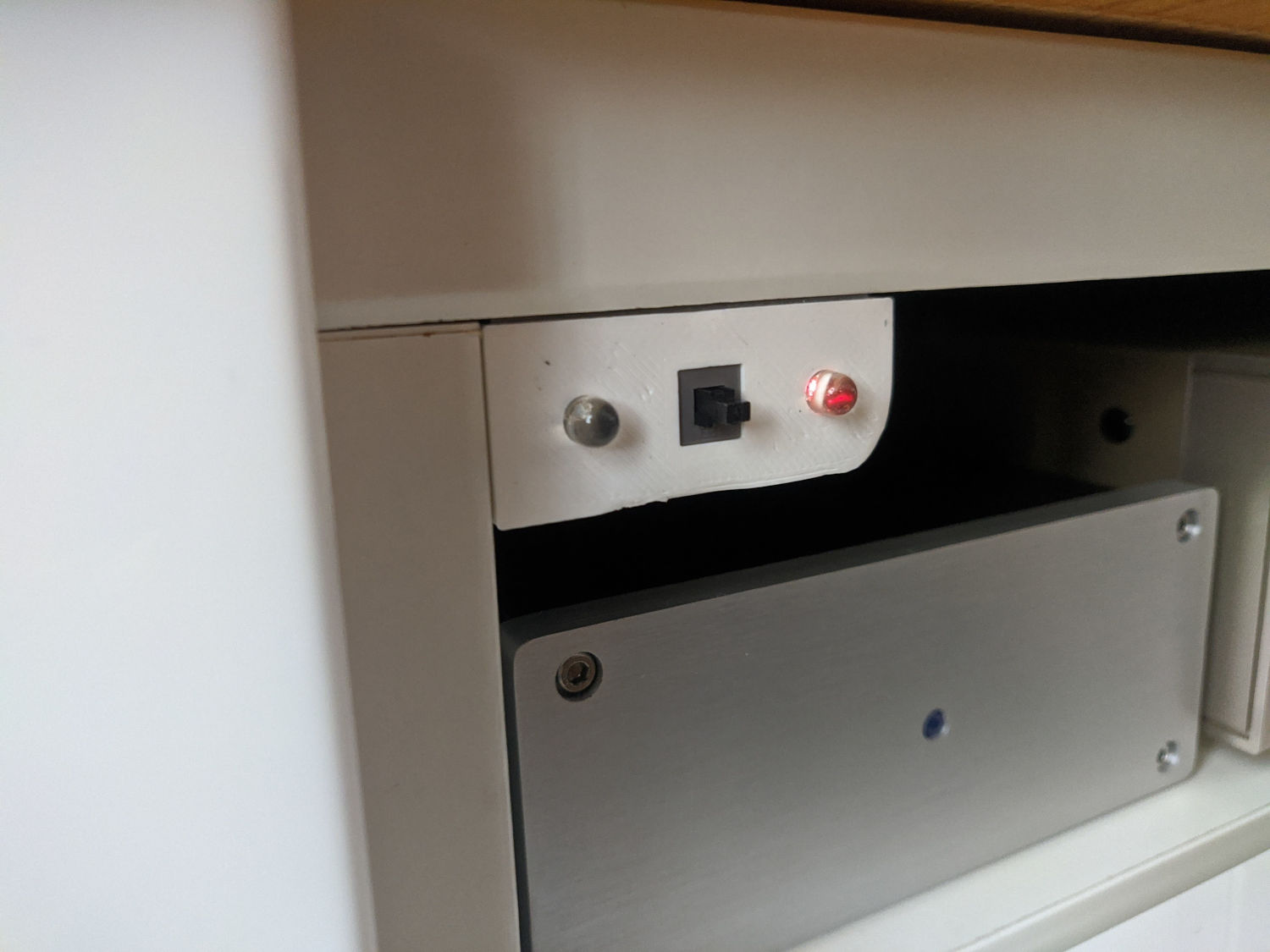
Here it is in all its uglyness.
Front Panel
Front panel CAD. Front panel completed and mounted. It’s incredible how cheap these buttons are while still feeling pretty good.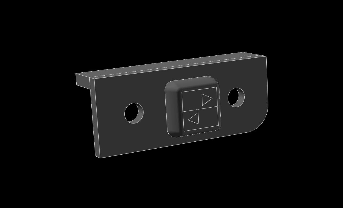
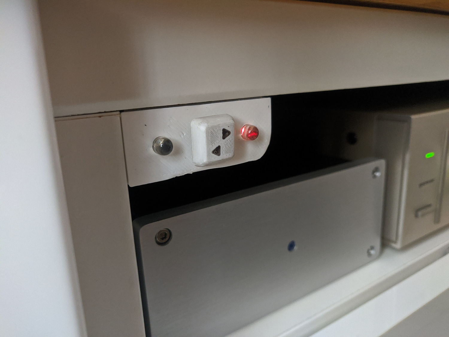
The front panel is the local interface to the switch. It contains a momentary push-button to toggle input and two press-fitted LEDs that indicate the selected one. Front panel’s back side. Here you can see the button retainer clip. Front panel without the keycap.
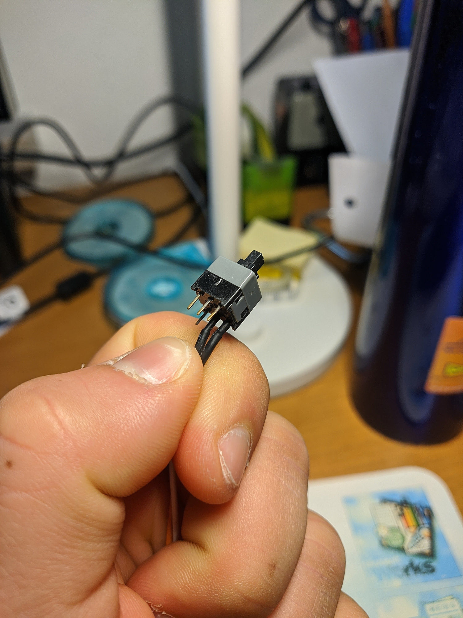
The button I used came from a PC front panel power button. Searching online for “pc power switch” I found it is produced by many manufacturers and can be found for just a few cents.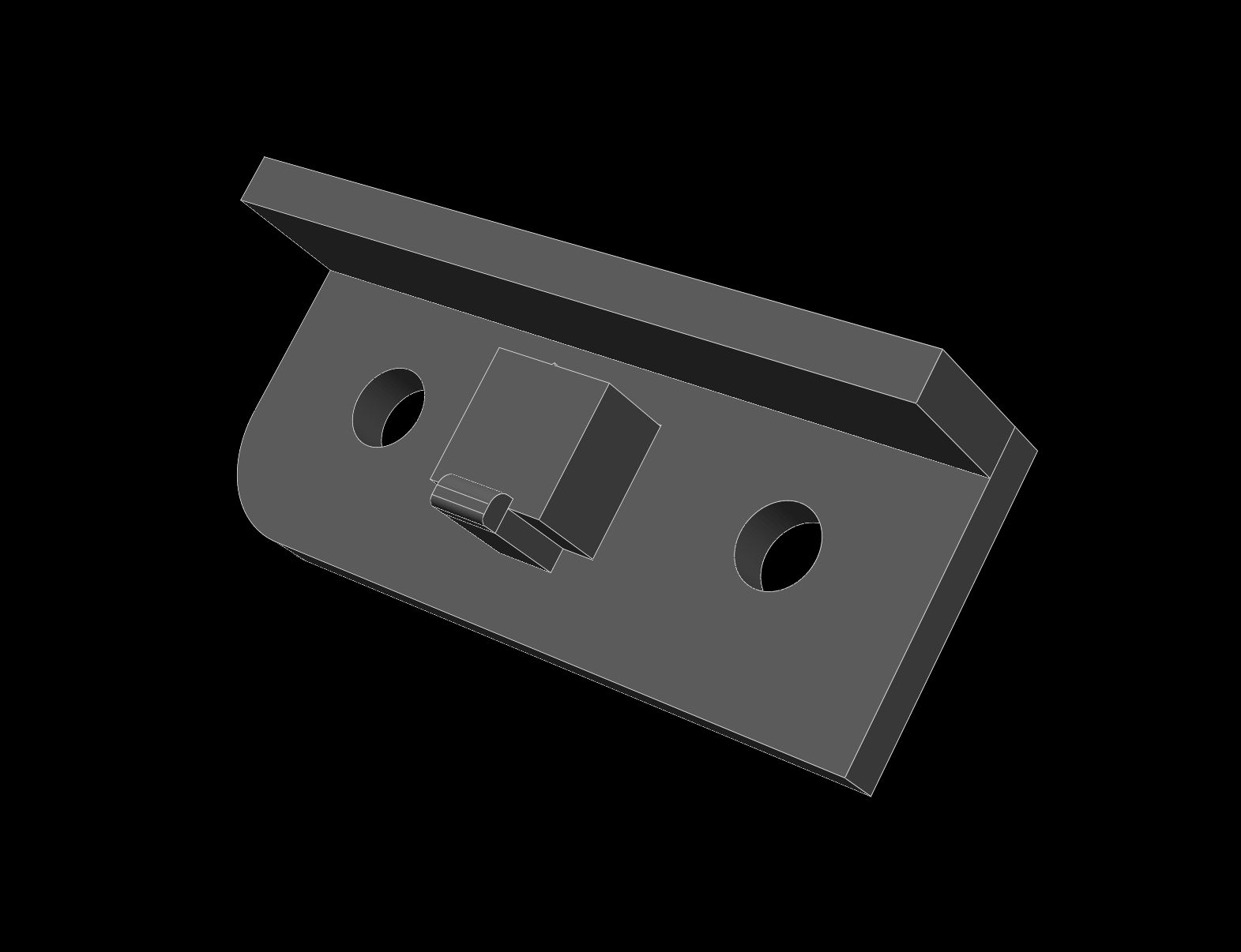
I designed a keycap to go on the switch along with a mounting for the front panel. Since I am sort of a keyboard nerd, the black legend is actually 3D-printed by first printing the legend, which is just a single layer thick, then the filament is swapped while the bed is kept hot, and the rest of the cap is printed.
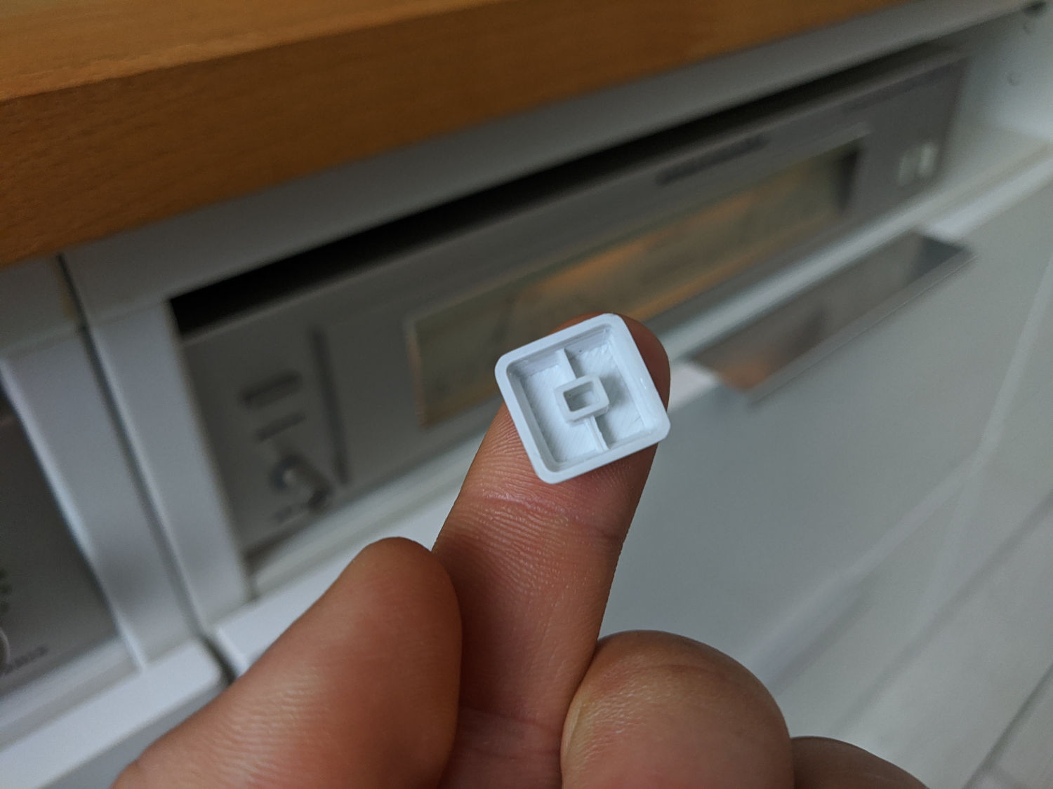
Back of the keycap with stem and it’s reinforcement. It’s a miniature keyboard keycap basically. So cute.
Software
Instead of reinventing the wheel writing custom ESP8266 firmware, I just flashed Tasmota on the ESP-01 and linked it to Home Assistant through MQTT. I then set up two simple automations to automatically toggle the inputs.
automations.yaml:
alias: Switch to Chromecast Audio
description: Switch audio source to Chromecast Audio
trigger:
  - entity_id: binary_sensor.chromecast_audio_status
    platform: state
    to: 'on'
  - entity_id: binary_sensor.tv_status
    platform: state
    to: 'off'
condition:
  - condition: state
    entity_id: binary_sensor.chromecast_audio_status
    state: 'on'
  - condition: state    # Don't switch to Chromecast Audio if TV is on
    entity_id: binary_sensor.tv_status
    state: 'off'
action:
  - service: switch.turn_on
    entity_id: switch.audio_switch
mode: single

alias: Switch to TV
description: Switch audio source to TV
trigger:
  - entity_id: binary_sensor.chromecast_audio_status
    platform: state
    to: 'off'
  - entity_id: binary_sensor.tv_status
    platform: state
    to: 'on'
condition:
  - condition: state
    entity_id: binary_sensor.tv_status
    state: 'on'
action:
  - service: switch.turn_off
    entity_id: switch.audio_switch
  - service: media_player.turn_off # Turn off other speaker if TV is on
    entity_id: media_player.other_speaker
mode: single
Conclusions
I’ve been using the switch for a couple of weeks without a single issue. Audio quality has not changed and it is very convenient to not touch the amplifier anymore. I will see how long the relay contacts hold up, but for the time being it’s working perfectly.
Here’s the repository with all the 3D models, pictures and schematics.